Mods - SV3EAO
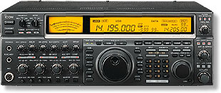
Icom 775 4.5 kHz eSSB
|
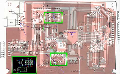
| Icom 775 Mods - Courtesy of SV3EAO - Fotis Visilias
If someone wants to experiment or try something
better, I have the radio's service manual and will entertain any
ideas with pleasure. I believe that the radio can TX out to 6 kHz
BW, but I haven't found free time from my QRL to check it.The overall
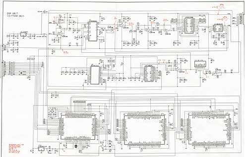
BW depends is dependent on the DSP unit only and the block diagrams
is- [AD converter, to limiter, to lowcut, to hicut, to line pre,
to DA converter.] For further information or details: e-Mail: visilias@yahoo.gr Website: http://www.qsl.net/sv3eao 73, Fotis Visilias - SV3EAO |
| Photos For Above Mods: Coutesy
of SV3EAO - Fotis Visilias |
| John M. Anning - NU9N
e-Mail: |
Home
| Intro | About |
Rx | Tx | Extended
SSB | AM | Rec/Play
| Photos | Feedback
| Sites | MP3
Apologetics 1 | Apologetics 2 | Audio Glossary | Donate | eSSB Mods | eSSB Ready Rigs | Transmitter Settings for eSSB
File Downloads | News | Radio Connections | Transmitter Settings | Scope Your Audio | Site Map | Site Search | T-Pad Calculator
Apologetics 1 | Apologetics 2 | Audio Glossary | Donate | eSSB Mods | eSSB Ready Rigs | Transmitter Settings for eSSB
File Downloads | News | Radio Connections | Transmitter Settings | Scope Your Audio | Site Map | Site Search | T-Pad Calculator


